
Discrete Class-A Headphone Amplifier
This circuit is a discrete Class-A headphone amplifier powered from symmetrical +/-15V supply rails (left channel shown only, the right channel is identical).
Unlike a conventional Class-AB headphone amplifier, where each output transistor only conducts for approximately half of the signal cycle, this design biases the output stage so that both output transistors conduct continuously. The result is an output stage that never switches between devices, eliminating crossover distortion and producing extremely linear operation. The trade-off is considerably higher quiescent power dissipation, making adequate heatsinking of the output transistors essential even when no headphones are connected.
Technically speaking, this is what's known as a "pseudo" Class-A. That is, it's in Class-A operation up until about 1/3 of its output power. After which it then operates in Class-AB.
Why Discrete?
I could have gone with a standard op-amp configuration with a Class-A output stage using transistors, however I wanted to design each stage myself. I like challenges! I also do not trust, or recommend, using the classic NE5532 (which have enough current drive on their own to not need an output stage - and can drive up to 600 ohm loads). The reason being, as of December 2025, Texas Instruments (TI) completely changed - and in my option nerfed - the design. The slew rate of the newer chips are worse, the 600 ohm drive capability has just vanished from the datasheet, the maximum supply voltage is now only +/-18V compared to the original +/-22V. Also, the internal circuitry is a completely different design, and is nowhere near similar.
I have absolutely no idea why they did that, but they basically ruined a very rugged and reliable jelly-bean op-amp. Luckily, they haven't changed the NE5534 - yet. The TL071 has also suffered at the hands of TI where the offset-null pins are no longer supported or internally connected. What?!
Other manufacturers of the NE5532 still use the original circuit, so if I wanted to, I'd just have to make sure the part is not a Texas Instruments' - including any further new circuits using it.
So, this is the reason for my approach to this circuit. However, I digress. The complete schematic is shown below.
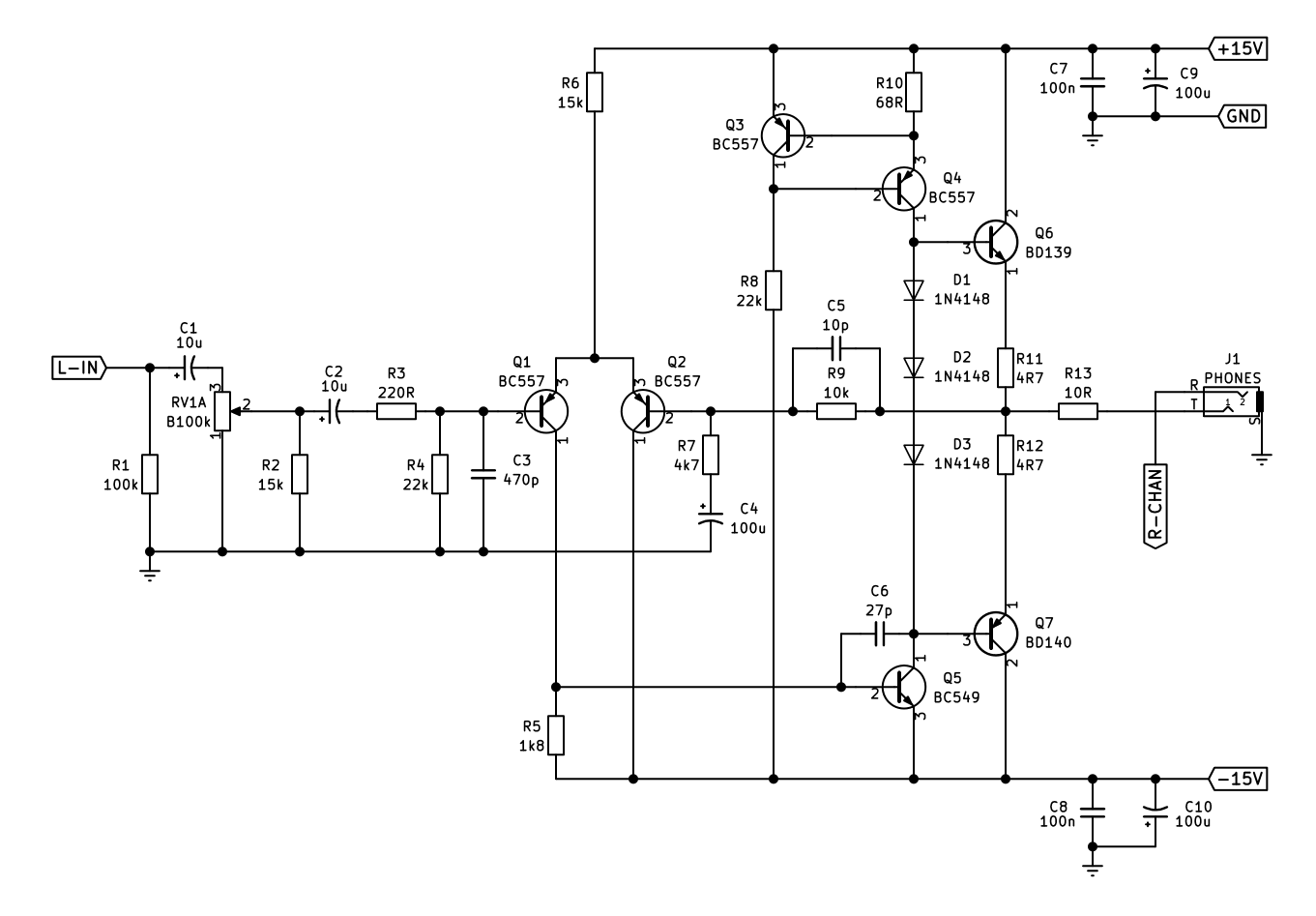
Fig. 1: schematic diagram of headphone amplifier. Only the left channel is shown, right channel is identical. With the supply voltages and component values shown, this amplifier can deliver up to 2W of output power into 32 ohms! Hearing damage would be permanent at that power. The amplifier itself should be fine with driving loads up to 120 ohms.
Circuit Description
The audio signal enters through capacitor C1, which blocks any DC from the source equipment while allowing the AC audio signal to pass into the volume control RV1A. Resistor R1 provides a DC return path for the input and establishes the input impedance. RV1A is a 100k linear potentiometer used as the volume control, varying the signal level presented to the amplifier without affecting its gain. The wiper feeds capacitor C2, which again blocks DC before the signal reaches the amplifier input stage. R2 provides a "log law" to the potentiometer; so through its rotation, the change in volume remains relatively logarithmic. Resistors R3 and R4 establish the input bias conditions, while capacitor C3 limits the high-frequency bandwidth to improve stability and reduce susceptibility to RF interference.
The first active stage is formed by Q1 and Q2, which make up a long-tailed differential pair. This stage is responsible for comparing the input signal with the amplifier's internal feedback signal and producing an error signal that drives the remainder of the amplifier. Differential input stages are widely used because they offer excellent linearity, high common-mode rejection, and provide a convenient point for applying negative feedback. In this circuit, the long-tailed pair establishes the foundation upon which the amplifier's low distortion performance is built.
The output of the differential pair drives Q5, a BC549 NPN transistor which forms the voltage amplification stage (VAS). This is the stage that provides the majority of the amplifier's open-loop voltage gain. Small changes at the collector of the differential pair are converted into large voltage swings by Q5, allowing the amplifier to produce enough drive voltage for the output stage. Capacitor C5 provides dominant-pole frequency compensation (often known as a "Miller" capacitor) around the VAS, ensuring the amplifier remains stable when global negative feedback is applied.
Unlike many simpler amplifier designs where the VAS is supplied through a resistor, this circuit uses Q3 and Q4 as an active constant-current source (CCS) for Q5. These two BC557 transistors maintain an almost constant collector current through the voltage amplification stage regardless of supply voltage fluctuations or output signal conditions. By forcing the VAS to operate from a stable current source rather than a resistor, the stage exhibits higher gain, improved linearity and better power supply rejection. This is a common technique used in high-performance discrete amplifier designs because it allows the VAS to operate under much more ideal conditions. Without the CCS, the positive cycle will clip way too early compared to the the negative cycle as there isn't enough drive; resulting in the amplifier only being able to deliver about 2/3rds it's power capability.
The output of the VAS feeds the complementary emitter-follower output stage consisting of Q6 (BD139) and Q7 (BD140). These transistors provide current gain rather than voltage gain, allowing the amplifier to drive relatively low impedance headphones without placing excessive load on the preceding voltage gain stages. Because emitter followers have a voltage gain close to unity, their role is simply to reproduce the voltage developed by the VAS while supplying the large output currents demanded by the headphones.
Biasing of the output stage is established by D1 to D3. The three forward-biased silicon diodes develop approximately 1.8 to 2 volts, which is sufficient to keep both output transistors partially conducting at all times. This produces a quiescent current of approximately 93mA through the output stage, placing the amplifier firmly into Class-A operation. Since the current never falls to zero in either transistor, there is no transition between positive and negative devices, completely eliminating crossover distortion. The trade-off is efficiency. Even when no audio is present, Q6 and Q7 continuously dissipate power as heat, making proper adequate heatsinking essential for reliable operation; this is a must, not a suggestion.
Resistors R11 and R12 are low-value emitter resistors that improve current sharing (or emitter "degeneration"), enhance thermal stability, and reduce the risk of thermal runaway by providing local negative feedback within the output stage. Output resistor R13 isolates the amplifier from highly capacitive headphone cables and improves stability under difficult loading conditions, as well as forms a crude short-circuit protection.
Finally, C6 to C9 provide local supply decoupling on the +/-15 V rails. The larger 100u electrolytic capacitors supply transient current during musical peaks, while the 100n capacitors provide low impedance at high frequencies, preventing oscillation and ensuring the amplifier remains stable across the entire audio bandwidth.
Conclusion
Overall, this amplifier follows the same architecture found in many high-quality discrete audio amplifiers. The long-tailed pair (Q1 and Q2) performs the error comparison, Q5 provides the high voltage gain as the Voltage Amplification Stage, Q3 and Q4 act as a constant-current source that optimises the VAS operating conditions, and Q6 and Q7 form a heavily biased complementary Class-A emitter-follower output stage. Although the continuous 93mA bias current results in greater heat dissipation and lower efficiency than a Class-AB design, it eliminates crossover distortion and produces the smooth, highly linear performance for which Class-A amplifiers are well known.
Unlike a conventional Class-AB headphone amplifier, where each output transistor only conducts for approximately half of the signal cycle, this design biases the output stage so that both output transistors conduct continuously. The result is an output stage that never switches between devices, eliminating crossover distortion and producing extremely linear operation. The trade-off is considerably higher quiescent power dissipation, making adequate heatsinking of the output transistors essential even when no headphones are connected.
Technically speaking, this is what's known as a "pseudo" Class-A. That is, it's in Class-A operation up until about 1/3 of its output power. After which it then operates in Class-AB.
Why Discrete?
I could have gone with a standard op-amp configuration with a Class-A output stage using transistors, however I wanted to design each stage myself. I like challenges! I also do not trust, or recommend, using the classic NE5532 (which have enough current drive on their own to not need an output stage - and can drive up to 600 ohm loads). The reason being, as of December 2025, Texas Instruments (TI) completely changed - and in my option nerfed - the design. The slew rate of the newer chips are worse, the 600 ohm drive capability has just vanished from the datasheet, the maximum supply voltage is now only +/-18V compared to the original +/-22V. Also, the internal circuitry is a completely different design, and is nowhere near similar.
I have absolutely no idea why they did that, but they basically ruined a very rugged and reliable jelly-bean op-amp. Luckily, they haven't changed the NE5534 - yet. The TL071 has also suffered at the hands of TI where the offset-null pins are no longer supported or internally connected. What?!
Other manufacturers of the NE5532 still use the original circuit, so if I wanted to, I'd just have to make sure the part is not a Texas Instruments' - including any further new circuits using it.
So, this is the reason for my approach to this circuit. However, I digress. The complete schematic is shown below.
Fig. 1: schematic diagram of headphone amplifier. Only the left channel is shown, right channel is identical. With the supply voltages and component values shown, this amplifier can deliver up to 2W of output power into 32 ohms! Hearing damage would be permanent at that power. The amplifier itself should be fine with driving loads up to 120 ohms.
Circuit Description
The audio signal enters through capacitor C1, which blocks any DC from the source equipment while allowing the AC audio signal to pass into the volume control RV1A. Resistor R1 provides a DC return path for the input and establishes the input impedance. RV1A is a 100k linear potentiometer used as the volume control, varying the signal level presented to the amplifier without affecting its gain. The wiper feeds capacitor C2, which again blocks DC before the signal reaches the amplifier input stage. R2 provides a "log law" to the potentiometer; so through its rotation, the change in volume remains relatively logarithmic. Resistors R3 and R4 establish the input bias conditions, while capacitor C3 limits the high-frequency bandwidth to improve stability and reduce susceptibility to RF interference.
The first active stage is formed by Q1 and Q2, which make up a long-tailed differential pair. This stage is responsible for comparing the input signal with the amplifier's internal feedback signal and producing an error signal that drives the remainder of the amplifier. Differential input stages are widely used because they offer excellent linearity, high common-mode rejection, and provide a convenient point for applying negative feedback. In this circuit, the long-tailed pair establishes the foundation upon which the amplifier's low distortion performance is built.
The output of the differential pair drives Q5, a BC549 NPN transistor which forms the voltage amplification stage (VAS). This is the stage that provides the majority of the amplifier's open-loop voltage gain. Small changes at the collector of the differential pair are converted into large voltage swings by Q5, allowing the amplifier to produce enough drive voltage for the output stage. Capacitor C5 provides dominant-pole frequency compensation (often known as a "Miller" capacitor) around the VAS, ensuring the amplifier remains stable when global negative feedback is applied.
Unlike many simpler amplifier designs where the VAS is supplied through a resistor, this circuit uses Q3 and Q4 as an active constant-current source (CCS) for Q5. These two BC557 transistors maintain an almost constant collector current through the voltage amplification stage regardless of supply voltage fluctuations or output signal conditions. By forcing the VAS to operate from a stable current source rather than a resistor, the stage exhibits higher gain, improved linearity and better power supply rejection. This is a common technique used in high-performance discrete amplifier designs because it allows the VAS to operate under much more ideal conditions. Without the CCS, the positive cycle will clip way too early compared to the the negative cycle as there isn't enough drive; resulting in the amplifier only being able to deliver about 2/3rds it's power capability.
The output of the VAS feeds the complementary emitter-follower output stage consisting of Q6 (BD139) and Q7 (BD140). These transistors provide current gain rather than voltage gain, allowing the amplifier to drive relatively low impedance headphones without placing excessive load on the preceding voltage gain stages. Because emitter followers have a voltage gain close to unity, their role is simply to reproduce the voltage developed by the VAS while supplying the large output currents demanded by the headphones.
Biasing of the output stage is established by D1 to D3. The three forward-biased silicon diodes develop approximately 1.8 to 2 volts, which is sufficient to keep both output transistors partially conducting at all times. This produces a quiescent current of approximately 93mA through the output stage, placing the amplifier firmly into Class-A operation. Since the current never falls to zero in either transistor, there is no transition between positive and negative devices, completely eliminating crossover distortion. The trade-off is efficiency. Even when no audio is present, Q6 and Q7 continuously dissipate power as heat, making proper adequate heatsinking essential for reliable operation; this is a must, not a suggestion.
Resistors R11 and R12 are low-value emitter resistors that improve current sharing (or emitter "degeneration"), enhance thermal stability, and reduce the risk of thermal runaway by providing local negative feedback within the output stage. Output resistor R13 isolates the amplifier from highly capacitive headphone cables and improves stability under difficult loading conditions, as well as forms a crude short-circuit protection.
Finally, C6 to C9 provide local supply decoupling on the +/-15 V rails. The larger 100u electrolytic capacitors supply transient current during musical peaks, while the 100n capacitors provide low impedance at high frequencies, preventing oscillation and ensuring the amplifier remains stable across the entire audio bandwidth.
Conclusion
Overall, this amplifier follows the same architecture found in many high-quality discrete audio amplifiers. The long-tailed pair (Q1 and Q2) performs the error comparison, Q5 provides the high voltage gain as the Voltage Amplification Stage, Q3 and Q4 act as a constant-current source that optimises the VAS operating conditions, and Q6 and Q7 form a heavily biased complementary Class-A emitter-follower output stage. Although the continuous 93mA bias current results in greater heat dissipation and lower efficiency than a Class-AB design, it eliminates crossover distortion and produces the smooth, highly linear performance for which Class-A amplifiers are well known.