
ETI-480 100W Power Amplifier - Second Edition
__NOTE__: Gerber files for PCBs will be available for purchase from my Patreon as soon as I have had them manufactured myself and tested the module and am happy with it.
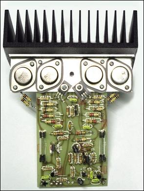
The ETI-480 power amplifier module was a very popular DIY project from the late 1970's well in to the late 1990's. Silicon Chip magazine did make a revamped version of it in January 2003 (called the SC480); but it was really a completely different design to the original, using a differential VAS and an emitter-follower output stage instead of the complimentary feedback pairs.
Originally, the ETI-480 was based on the ETI-422 published in July 1974 of the ETI magazine Australia by David Tilbrook. Tilbrook also worked on the classic ETI-413 as well, which was a popular 100W guitar amplifier module. Subsequently, the ETI-480 was adapted from the ETI-422 and "debugged" by Col Chapman, who also added the so-called "100W" upgrade.
Below (fig. 1) is the schematic to the original 1977 ETI-480.
The classic original ETI-480
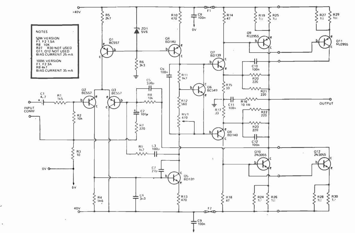
Fig. 1: the original schematic to the ETI-480, published March 1977
The amplifier itself is pretty conventional, however it suffers from a really bad upper frequency response, is prone to parasitic oscillations and has a few bad design choices. There is also a big red-flag that the amplifier has stability issues by the use of a 330p capacitor (C5) across the negative feedback resistor (R8). The value of this capacitor is suspiciously high, and removing it or lowering it greatly effects the frequency response - making it worse.
The first of the bad design choices is C4 (the 3n3 capacitor) connecting between the base of VAS transistor Q5 and the negative supply rail. This capacitor was most likely a "band-aid" fix to an oscillation problem, rather than actually fixing the real problem. Adding a capacitor there like that will affect the frequency response.
The second bad design choice is the placement of the fuses. Say, for example, in a short-circuit output condition; if any of the fuses blow, only the output stage is disconnected from the supply rail(s). The rest of the circuit, including the other side of the output stage where the fuse didn't blow still have power. This results in the remaining working side of the amplifier producing a badly distorted output in the speaker. The fuses should really be protecting the entire circuit/power supply rail(s).
The final bad design choice is the negative-feedback closed-loop gain boosting of the output stage (R15, R17, R20 to R23, C10 and C12). With the current values, the closed-loop gain of the output stage is boosted by around 4.3 times (about +12.7dB). When driving to full power, the original 1W resistors are barely large enough to dissipate the current. C10 and 12 just help prevent the output stage going in to oscillation. Doug Self has mentioned in his "Power Amplifier Design Handbook" the benefits to boosting the gain of the output stage like this in an attempt to squeeze every last watt out of it isn't worth the effort.
So, now we'll move on to my second edition version of fig. 2 below.
The New "Second Edition"
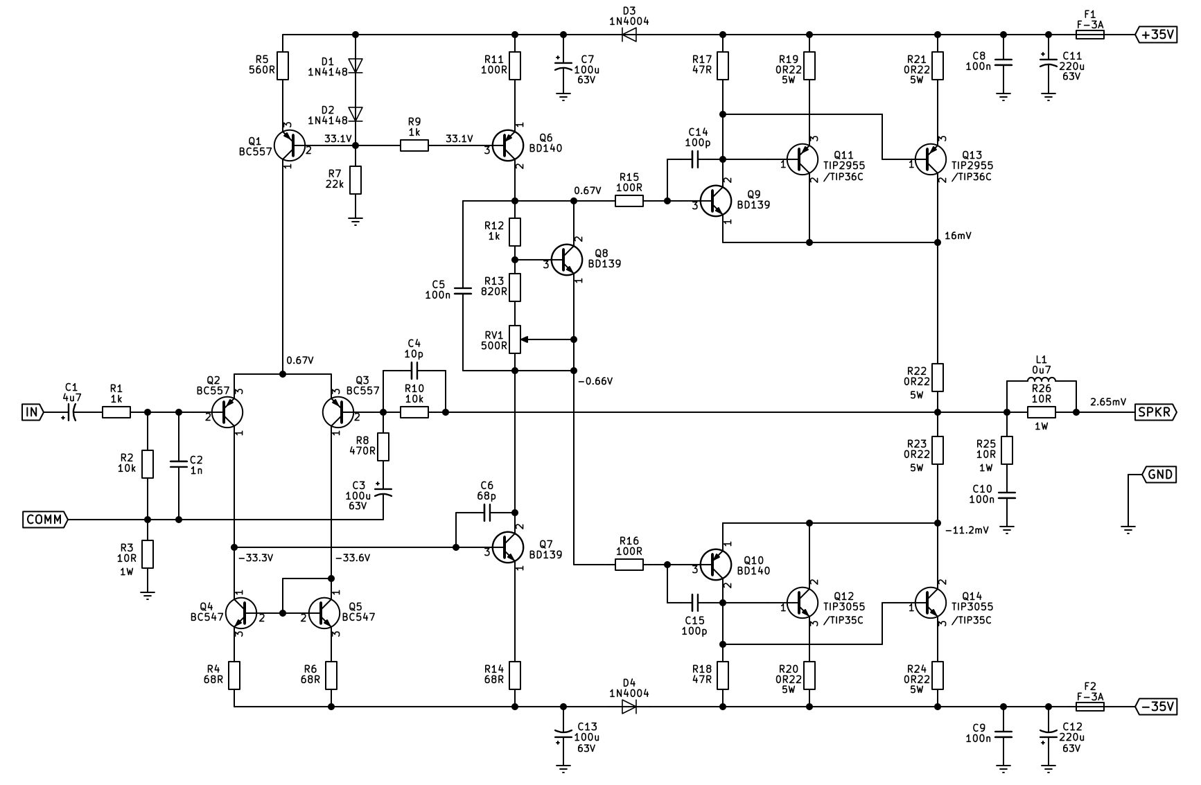
Fig. 2: schematic of the "revamped" second edition of the original ETI-480 with better stability and performance specifications. All voltages shown with reference to ground and with matched transistors.
As seen in the schematic above, it's pretty much the same only with the removal of the output gain boosting, addition of a current-mirror in the long-tail pair and a modified constant current source (Q1 and Q6). D3 and D4 were added to "isolate" the output stage/drivers from the low-current input stage. This is done to help prevent the input stage from "starving" for current in a large output transient that will cause the supply rail(s) to dip in voltage. This can also improve stability from unwanted oscillation as the amplifier is driving a load hard.
Addition of the current-mirror helps "force" equal current through both transistors of the long-tail pair and to keep distortion low. The constant current source was changed from the original 5.6V Zener diode to two 1N4148 series diodes and resistor values changed to lower the currents through the long-tail pair (1mA vs. 1.8mA of the original) and VAS (5.7mA vs. 10.7mA of the original) stages. Lowering these currents greatly improved the frequency response.
The final addition is the parallel inductor/resistor combination (L1 and R26) which helps keep the amplifier stable at higher frequencies when driving a capacitive load.
Total harmonic distortion (THD) - at least as far as the simulation goes, is fairly low at 0.03% at full power into 8 ohms. I suspect this will be lower in the real-world, as TINA tends to not accurately represent a lot of things.
Comparisons
All performance analysis was done using the TINA-TI simulation software. I will say up-front that this isn't a definitive good or bad analysis, as there could be a few discrepancies in the transistor models used skewing the results. However, it does give us a good A and B side-by-side comparison.
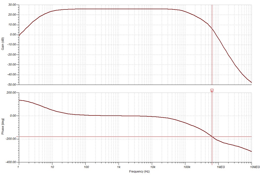
Fig. 3: Original ETI-480 frequency response and phase curve
Looking at the above graph of fig. 3, the overall frequency response isn't really that bad; however, the phase curve at the upper end 180 degree shift is below 1MHz - 644kHz to be exact. This can cause HF oscillation. Now, we compare the bode plot of the ETI-480 second edition below.
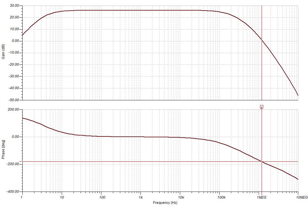
Fig. 4: ETI-480SE frequency response and phase curve
As we can see, the phase curve at the upper end of the spectrum is above 1MHz (1.18MHz) at the 180 degree crossover point. The curve itself should really be more of steeper declines; however, as mentioned above, it could be the chosen models for the transistors of the simulation being not quite right.
Real-world tests
The SE was built up on breadboard to test the circuit's actual operation. With my test setup of +/-31V DC as the supply rails, output power into 8 ohms with only a single output pair is 41W. Which is not bad, and to be expected. The main issue I had originally was the bias being unstable. The problem was the Vbe multiplier wasn't tracking the driver transistors (as they're not connected to the main heatsink in this setup), so it was the drivers themselves going in to early thermal runaway. Moving the Vbe multiplier to be in contact with one of the drivers fixed the issue.
Speaking of bias; I have it sitting at an Iq of around 29mA. That's a 6.5mV voltage drop across R23. If both output pairs were connected, the Iq would be set by measuring the voltage drop of R19.
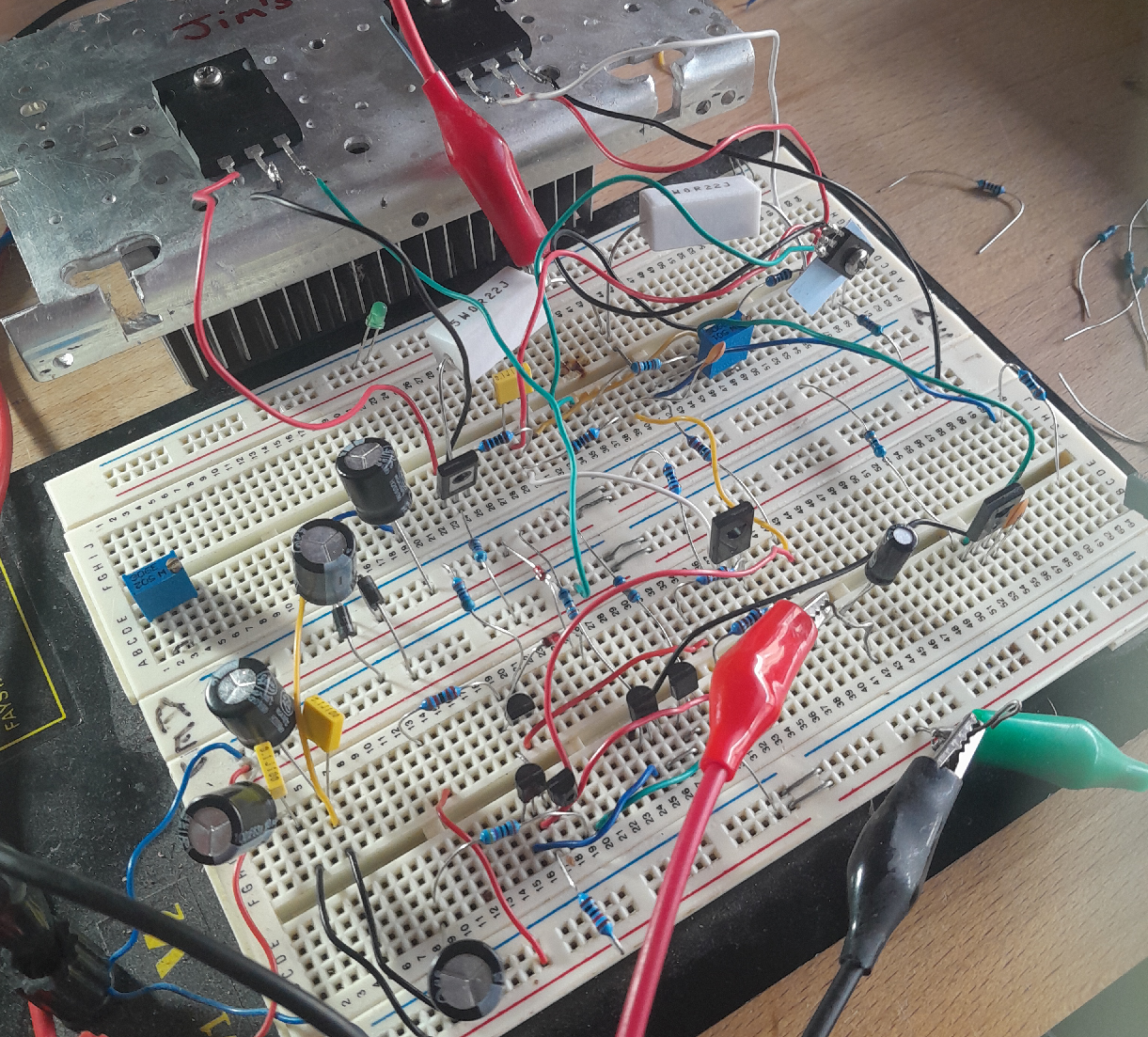
Fig. 5: a rather messy breadboard layout testing the amplifier. Ignore the trimpot on the left of the breadboard; this isn't part of the circuit.
Breadboard really isn't a good medium for testing power amplifiers (or anything current sensitive, and definitely bad for RF circuits), due to added capacitances of the strip connections. However, it does help in making sure that the simulation matches reality - which it seems to do just nicely.
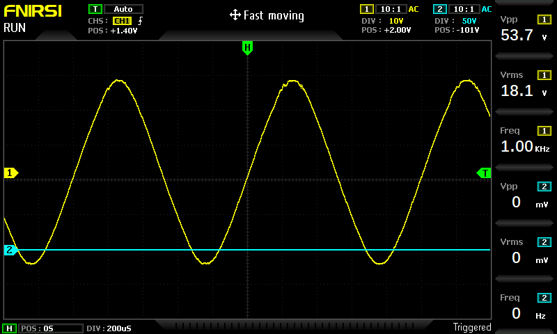
Fig. 6: amplifier full power output before clipping
Output power into 8 ohms before clipping is shown in fig. 6 above. This shows us at +/-31V DC supply rails even with a single output pair, we get 40.95W (almost 41W mentioned earlier). Which is nice! At +/-35V DC supply rails, I'd expect this power to be closer to 50W into 8 ohms. Incidentally, the output power into 4 ohms is 66W at +/-31V DC.
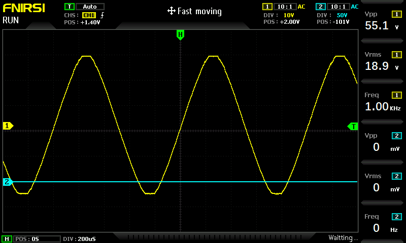
Fig. 7: amplifier at onset of clipping
As can be seen from fig. 7, the amplifier appears to clip symmetrically (into 8 ohms) - which is good. This indicates the VAS and driver transistors have the correct amount of voltage drive.
New PCB
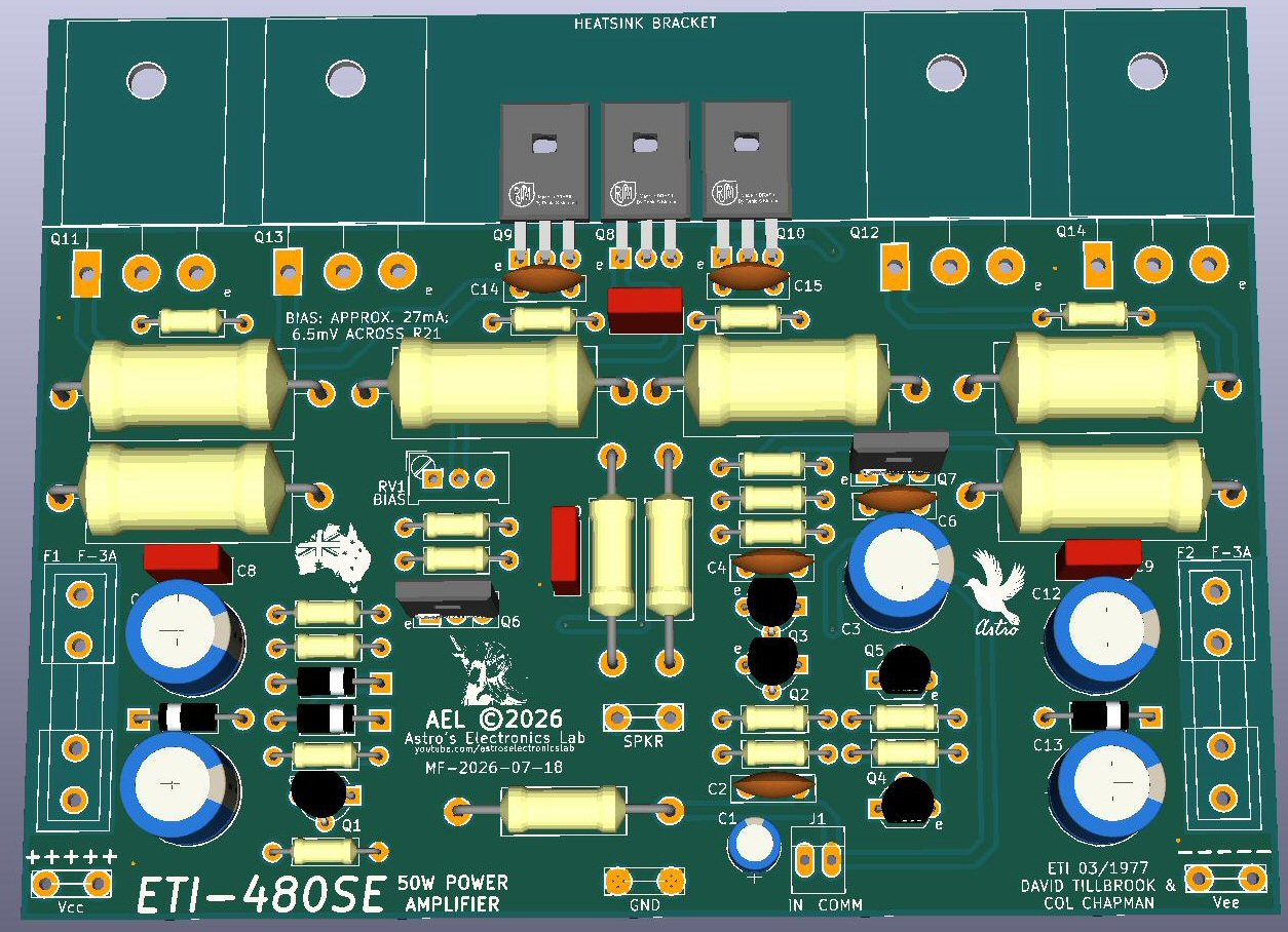
Fig. 8: 3D render of the proposed new PCB for the SE of the amplifier
And, of course, I've spent the time to route a new PCB for it. At some point, I will have it manufactured and test it on my YouTube channel and eventually make the gerber files available for download on my Patreon for the small fee of $3 US. This is with the request that they are not to re-distributed, uploaded anywhere else or mass produced as kits.
Conclusion
The original ETI-480 was regarded as a "rugged" amplifier but there was room for vast improvements. Thousands of these modules were sold as kits by Dick Smith and Jaycar and they did perform generally well. I built a few of them over the years, including the SC480, and never had one of them suffer stability issues. Having said that, even though my second edition is only barely resembling the 480; it will perform just as well, if not better, than the original.