
CFP Amplifier Output Stage with Closed-Loop Gain Boosting
In this short article, I've included a quick equation for calculating the gain of the following complimentary-feedback pair output stage that includes a voltage divider to provide local negative-feedback to the drivers to boost the gain of the output stage.
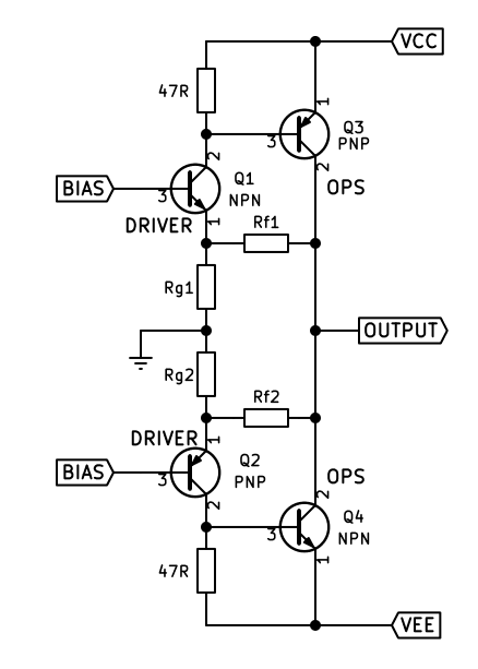
Fig. 1: example CFP output stage with voltage dividers to boost the gain
In the above schematic, ignoring the values of the 47 ohm resistors (as they may differ from design to design), we will just focus on the resistors Rf1/2 and Rg1/2. The formula to calculate the effective output gain of the CFP stage is as follows:
Av = Rf1 + Rg1 / Rg1
we only concern ourselves with one of the dividers. So, take for example the value of Rf1 was 110 ohms, and the value of Rg1 was 33 ohms (and Rf2 and Rg2 should/would be the same values by the way, as it's symmetrical), then the calculation would be as follows:
**Av = 110 + 33 / 33
Av = 143 / 33
Av = 4.33**
so, 4.3 times. The above values were based on the ETI-480's output stage as I wanted to know how to calculate the gain.
If we were to calculate this in decibels, then we would do the following:
**Av = log(4.33) * 20
Av = +12.7dB**
Douglas Self has stated in his Power Amplifier Design Handbook about doing this closed-loop negative-feedback gain boosting of a CFP output stage:
**//" Output stages with gain can be made to work, but ultimately my advice would be that you probably
do not want to go this way."//**
with good reason. As stability of the output stage becomes a huge problem. The other problem is, if you get the values of the resistors wrong, the power dissipation through the resistors becomes another problem; which could lead to using 5 - 10W resistors taking up huge amounts of PCB space.
Fig. 1: example CFP output stage with voltage dividers to boost the gain
In the above schematic, ignoring the values of the 47 ohm resistors (as they may differ from design to design), we will just focus on the resistors Rf1/2 and Rg1/2. The formula to calculate the effective output gain of the CFP stage is as follows:
Av = Rf1 + Rg1 / Rg1
we only concern ourselves with one of the dividers. So, take for example the value of Rf1 was 110 ohms, and the value of Rg1 was 33 ohms (and Rf2 and Rg2 should/would be the same values by the way, as it's symmetrical), then the calculation would be as follows:
**Av = 110 + 33 / 33
Av = 143 / 33
Av = 4.33**
so, 4.3 times. The above values were based on the ETI-480's output stage as I wanted to know how to calculate the gain.
If we were to calculate this in decibels, then we would do the following:
**Av = log(4.33) * 20
Av = +12.7dB**
Douglas Self has stated in his Power Amplifier Design Handbook about doing this closed-loop negative-feedback gain boosting of a CFP output stage:
**//" Output stages with gain can be made to work, but ultimately my advice would be that you probably
do not want to go this way."//**
with good reason. As stability of the output stage becomes a huge problem. The other problem is, if you get the values of the resistors wrong, the power dissipation through the resistors becomes another problem; which could lead to using 5 - 10W resistors taking up huge amounts of PCB space.