
555 Timer Circuits: Police Car Flashing Lights
__NOTE 1__: This circuit has been updated here as it's probably not a good idea to run parallel LEDs directly on the CD4017's outputs.
This circuit is a simple electronic flasher designed to imitate the warning lights found on police and emergency vehicles - perfect for models and toys. It uses two very common integrated circuits: an NE555 timer, which generates a continuous stream of clock pulses, and a CD4017 decade counter, which sequences those pulses into a repeating pattern. Rather than simply alternating between red and blue LEDs, the outputs of the 4017 are deliberately combined with steering diodes so that the LEDs flash in short bursts. The result is a much more realistic effect, with the blue LEDs flashing three times before the red LEDs flash three times, continuously repeating.
__NOTE 2__: It is illegal to put flashing red and blue lights on a real non-emergency vehicle. Impersonating law enforcement by fitting such a circuit as this to your car could wind up with big legal issues.
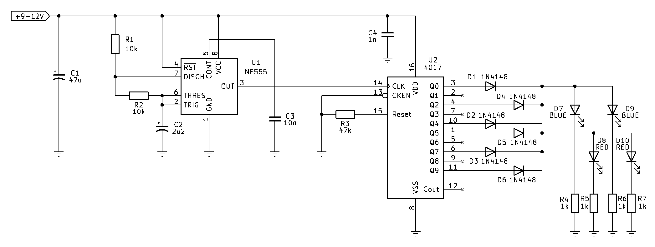
Fig. 1: schematic of the police car flashing red and blue lights
Circuit Description
The supply voltage can be anywhere from approximately 9 to 12 volts. Capacitor C1 provides bulk supply filtering to smooth any voltage dips caused by the LEDs switching on and off, while C4 is a high-frequency bypass capacitor placed close to the CD4017 to suppress switching noise and ensure reliable operation.
The flashing sequence begins with U1, the NE555 timer configured as an astable oscillator. In this mode the 555 continuously generates a square-wave output without requiring any external trigger. Resistors R1 and R2, together with timing capacitor C2, determine the oscillation frequency. Capacitor C2 repeatedly charges through R1 and R2 until its voltage reaches approximately two-thirds of the supply voltage. At this point the internal threshold comparator causes the output to change state and turns on the discharge transistor connected to pin 7. Capacitor C2 then discharges through R2 until its voltage falls to roughly one-third of the supply voltage, whereupon the trigger comparator switches the output back again. This charge and discharge cycle repeats continuously, producing a stream of clock pulses at pin 3. Capacitor C3, connected to the control voltage pin, improves stability by filtering noise that might otherwise alter the switching thresholds of the timer. The timer oscillates at around 20Hz with a 66% duty cycle.
Each pulse from the NE555 is fed directly to the clock input of the CD4017 decade counter. The 4017 advances one output on every rising clock edge so that only one output is high at any given time. Normally the counter would step sequentially through outputs Q0 to Q9 before repeating. However, this circuit intentionally uses only selected outputs and combines them using steering diodes to create a more complex flashing pattern.
The reset pin (pin 15) is held low through R3, allowing the counter to run continuously. The clock enable input (CKEN) is also held in the correct state so that counting is never inhibited.
The clever part of the design is the diode steering network formed by D1 to D6. Instead of connecting one LED to each output, several counter outputs are diode-ORed together. This allows multiple count positions to illuminate the same LED colour while leaving gaps where no LEDs are driven. Those gaps create the impression of rapid flickering rather than a steady rhythm.
Outputs Q0, Q2 and Q4 are routed through D1, D2 and D4 to the blue LED bus. Each time the counter reaches one of these outputs, both blue LEDs D7 and D9 illuminate simultaneously through current-limiting resistors R4 and R6. Between these outputs, the unused outputs briefly turn the LEDs off, so the observer sees three distinct blue flashes rather than one long flash.
After the blue sequence has completed, the counter advances further until outputs Q5, Q7 and Q9 become active. These outputs are combined through D5, D3 and D6 to drive the red LED bus. The two red LEDs D8 and D10 then flash together through resistors R5 and R7, again producing three separate flashes because the unused counter outputs create short dark intervals between each pulse.
The sequence therefore appears as:
Blue → Off → Blue → Off → Blue → Off → Red → Off → Red → Off → Red → Off → repeat.
Although the 4017 is still counting sequentially through its outputs, the unused outputs are effectively skipped because they are not connected to any LEDs. These skipped outputs introduce short pauses that break each colour into three individual flashes, giving the lights a flickering appearance similar to the flash patterns used on real emergency vehicles. Without this deliberate skipping, the LEDs would simply alternate between blue and red at a constant rate, producing a much less convincing effect.
One thing to note
Even though the circuit shows two sets of LEDs in parallel per colour, the CD4017 can only sink a maximum of 10mA per output; and that's in short bursts. It's best to either run a single LED per colour, or recalculate the LED's cathode resistors and limit the current to 1 - 2mA. To do this, you need to know the forward voltage of the LED (Vf) by looking at its datasheet, or measuring it.
The resistor is calculated as follows:
R = Vs - Vf / I
where Vs is the supply voltage, in this case we'll say 12V; Vf is the forward voltage of the LED, we'll choose an arbitrary value of 2.1V; and I is the current through the LED, which we'll limit to 1.5mA. So the calculation would be as follows:
**R = 12 - 2.1 / 0.0015
R = 9.9 / 0.0015
R = 6600 ohms**
So, 6.8k would be about right. The values of 1k shown in the schematic were based on running a single set of LEDs at 9mA. A better alternative (which I may post an updated circuit) is to use switching transistors to drive the LEDs off of the steering diodes.
Conclusion
Overall, the NE555 provides the timing, while the CD4017 determines the flash sequence. The diode steering network converts the simple one-of-ten counter outputs into alternating groups of three flashes, producing an eye-catching police-style light pattern using only a handful of inexpensive components.
If you find the flash rate appears a bit on the quick side, you can slow it down but modifying the RC network of the 555 (R1, R2 and C2) until you get a satisfactory effect. Have fun!
This circuit is a simple electronic flasher designed to imitate the warning lights found on police and emergency vehicles - perfect for models and toys. It uses two very common integrated circuits: an NE555 timer, which generates a continuous stream of clock pulses, and a CD4017 decade counter, which sequences those pulses into a repeating pattern. Rather than simply alternating between red and blue LEDs, the outputs of the 4017 are deliberately combined with steering diodes so that the LEDs flash in short bursts. The result is a much more realistic effect, with the blue LEDs flashing three times before the red LEDs flash three times, continuously repeating.
__NOTE 2__: It is illegal to put flashing red and blue lights on a real non-emergency vehicle. Impersonating law enforcement by fitting such a circuit as this to your car could wind up with big legal issues.
Fig. 1: schematic of the police car flashing red and blue lights
Circuit Description
The supply voltage can be anywhere from approximately 9 to 12 volts. Capacitor C1 provides bulk supply filtering to smooth any voltage dips caused by the LEDs switching on and off, while C4 is a high-frequency bypass capacitor placed close to the CD4017 to suppress switching noise and ensure reliable operation.
The flashing sequence begins with U1, the NE555 timer configured as an astable oscillator. In this mode the 555 continuously generates a square-wave output without requiring any external trigger. Resistors R1 and R2, together with timing capacitor C2, determine the oscillation frequency. Capacitor C2 repeatedly charges through R1 and R2 until its voltage reaches approximately two-thirds of the supply voltage. At this point the internal threshold comparator causes the output to change state and turns on the discharge transistor connected to pin 7. Capacitor C2 then discharges through R2 until its voltage falls to roughly one-third of the supply voltage, whereupon the trigger comparator switches the output back again. This charge and discharge cycle repeats continuously, producing a stream of clock pulses at pin 3. Capacitor C3, connected to the control voltage pin, improves stability by filtering noise that might otherwise alter the switching thresholds of the timer. The timer oscillates at around 20Hz with a 66% duty cycle.
Each pulse from the NE555 is fed directly to the clock input of the CD4017 decade counter. The 4017 advances one output on every rising clock edge so that only one output is high at any given time. Normally the counter would step sequentially through outputs Q0 to Q9 before repeating. However, this circuit intentionally uses only selected outputs and combines them using steering diodes to create a more complex flashing pattern.
The reset pin (pin 15) is held low through R3, allowing the counter to run continuously. The clock enable input (CKEN) is also held in the correct state so that counting is never inhibited.
The clever part of the design is the diode steering network formed by D1 to D6. Instead of connecting one LED to each output, several counter outputs are diode-ORed together. This allows multiple count positions to illuminate the same LED colour while leaving gaps where no LEDs are driven. Those gaps create the impression of rapid flickering rather than a steady rhythm.
Outputs Q0, Q2 and Q4 are routed through D1, D2 and D4 to the blue LED bus. Each time the counter reaches one of these outputs, both blue LEDs D7 and D9 illuminate simultaneously through current-limiting resistors R4 and R6. Between these outputs, the unused outputs briefly turn the LEDs off, so the observer sees three distinct blue flashes rather than one long flash.
After the blue sequence has completed, the counter advances further until outputs Q5, Q7 and Q9 become active. These outputs are combined through D5, D3 and D6 to drive the red LED bus. The two red LEDs D8 and D10 then flash together through resistors R5 and R7, again producing three separate flashes because the unused counter outputs create short dark intervals between each pulse.
The sequence therefore appears as:
Blue → Off → Blue → Off → Blue → Off → Red → Off → Red → Off → Red → Off → repeat.
Although the 4017 is still counting sequentially through its outputs, the unused outputs are effectively skipped because they are not connected to any LEDs. These skipped outputs introduce short pauses that break each colour into three individual flashes, giving the lights a flickering appearance similar to the flash patterns used on real emergency vehicles. Without this deliberate skipping, the LEDs would simply alternate between blue and red at a constant rate, producing a much less convincing effect.
One thing to note
Even though the circuit shows two sets of LEDs in parallel per colour, the CD4017 can only sink a maximum of 10mA per output; and that's in short bursts. It's best to either run a single LED per colour, or recalculate the LED's cathode resistors and limit the current to 1 - 2mA. To do this, you need to know the forward voltage of the LED (Vf) by looking at its datasheet, or measuring it.
The resistor is calculated as follows:
R = Vs - Vf / I
where Vs is the supply voltage, in this case we'll say 12V; Vf is the forward voltage of the LED, we'll choose an arbitrary value of 2.1V; and I is the current through the LED, which we'll limit to 1.5mA. So the calculation would be as follows:
**R = 12 - 2.1 / 0.0015
R = 9.9 / 0.0015
R = 6600 ohms**
So, 6.8k would be about right. The values of 1k shown in the schematic were based on running a single set of LEDs at 9mA. A better alternative (which I may post an updated circuit) is to use switching transistors to drive the LEDs off of the steering diodes.
Conclusion
Overall, the NE555 provides the timing, while the CD4017 determines the flash sequence. The diode steering network converts the simple one-of-ten counter outputs into alternating groups of three flashes, producing an eye-catching police-style light pattern using only a handful of inexpensive components.
If you find the flash rate appears a bit on the quick side, you can slow it down but modifying the RC network of the 555 (R1, R2 and C2) until you get a satisfactory effect. Have fun!