
555 Timer Circuits: Police Car Flashing Lights - Mk2
This circuit is a simple electronic flasher designed to imitate the warning lights found on police and emergency vehicles - perfect for models and toys. It uses two very common integrated circuits: an NE555 timer, which generates a continuous stream of clock pulses, and a CD4017 decade counter, which sequences those pulses into a repeating pattern. Rather than simply alternating between red and blue LEDs, the outputs of the 4017 are deliberately combined with steering diodes so that the LEDs flash in short bursts. The result is a much more realistic effect, with the blue LEDs flashing three times before the red LEDs flash three times, continuously repeating.
NOTE: It is illegal to put flashing red and blue lights on a real non-emergency vehicle. Impersonating law enforcement by fitting such a circuit as this to your car could wind up with big legal issues.
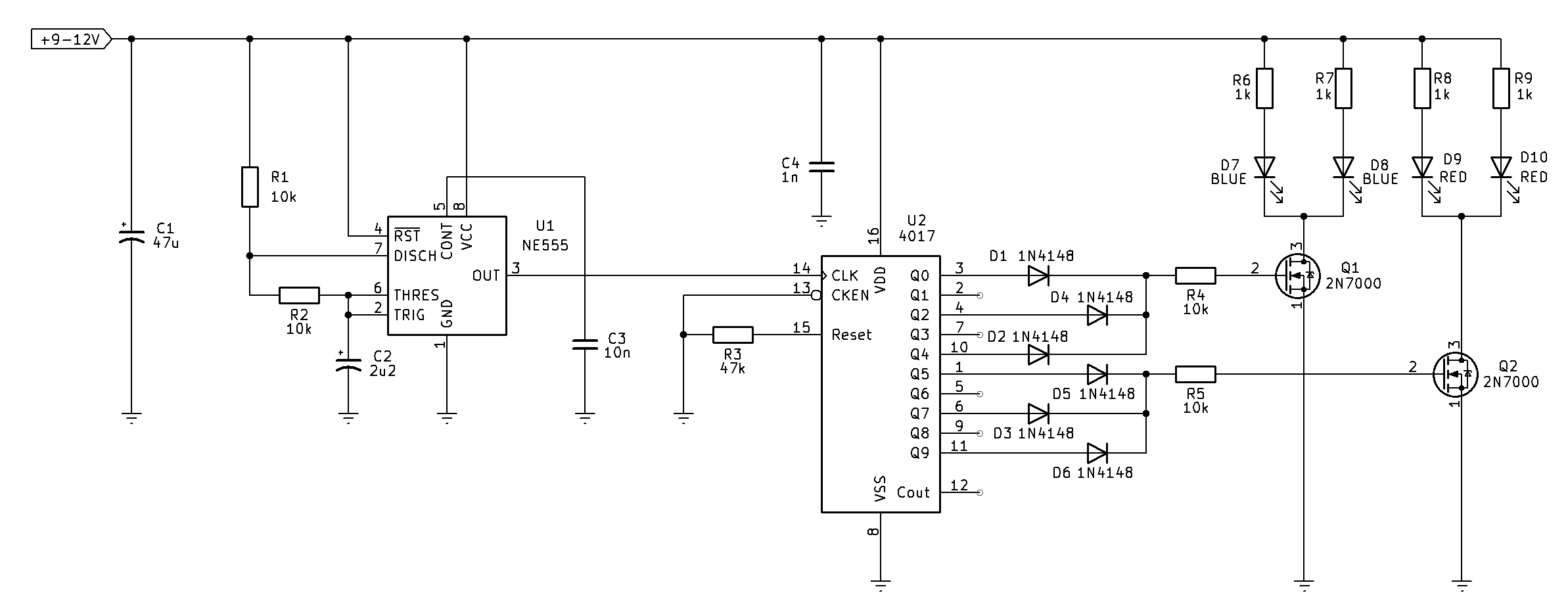
Fig. 1: schematic of the improved police car flashing lights
Circuit Description
This circuit operates on exactly the same principle as the previous design, using an NE555 timer to generate clock pulses and a CD4017 decade counter to produce the flashing sequence. The main difference is that the LEDs are no longer driven directly from the outputs of the CD4017. Instead, two 2N7000 N-channel MOSFETs are used as low-side switches, allowing the circuit to drive a much larger LED current while keeping the load on the CD4017 extremely light.
The circuit operates from a 9–12 V supply. Capacitor C1 provides bulk supply filtering, smoothing the incoming supply and preventing momentary voltage dips when the LEDs switch on. Capacitor C4 is a high-frequency bypass capacitor placed close to the CD4017 to reduce switching noise and ensure reliable logic operation.
The timing section is built around U1, an NE555 configured as an astable oscillator which runs at around 20Hz with a 66% duty cycle. In this configuration the timer continuously produces a square-wave output that serves as the system clock. Resistors R1 and R2, together with capacitor C2, determine the flash rate. Capacitor C2 repeatedly charges through R1 and R2 until its voltage reaches approximately two-thirds of the supply voltage. The internal comparator then switches the output low and turns on the discharge transistor connected to pin 7, allowing C2 to discharge through R2. Once the capacitor voltage falls to approximately one-third of the supply voltage, the timer switches high again and the cycle repeats. This continuous charging and discharging process produces a steady stream of clock pulses at pin 3. Capacitor C3, connected to the control voltage pin, filters internal reference noise and helps maintain a stable oscillation frequency.
Each pulse from the NE555 advances U2, the CD4017 decade counter, by one count. The 4017 activates one output at a time in sequence, progressing from Q0 through Q9 before returning to Q0. Pin 15, the reset input, is held low by R3, allowing the counter to run continuously, while the clock enable input is held in its active state so counting is never inhibited.
As with the previous circuit, the flashing pattern is created by selectively combining outputs with steering diodes. Outputs Q0, Q2, and Q4 are combined by D1, D4, and D2, while outputs Q6, Q8, and Q9 are combined by D5, D3, and D6. The unused outputs are intentionally left disconnected, producing short pauses between illuminated outputs. These pauses create the characteristic flickering appearance rather than a continuous flash.
The important difference in this version is what happens after the diode steering network. Instead of feeding LEDs directly, the diode outputs drive the gates of Q1 and Q2 through gate resistors R4 and R5. These resistors limit the gate charging current, suppress ringing caused by stray wiring inductance and capacitance, and ensure clean switching of the MOSFETs.
Transistor Q1 is responsible for switching the pair of blue LEDs D7 and D8, while transistor Q2 switches the pair of red LEDs D9 and D10. Each MOSFET operates as a low-side electronic switch. When the corresponding gate is driven high by one of the diode-combined outputs from the CD4017, the MOSFET turns fully on and provides a very low resistance path to ground. Current then flows from the positive supply through the current-limiting resistors R6 and R7, through the blue LEDs, through Q1, and finally to ground. Likewise, when the red output group becomes active, Q2 switches on and current flows through resistors R8 and R9, illuminating the two red LEDs.
Because the MOSFETs handle the LED current instead of the CD4017, the logic IC only needs to supply the tiny gate charging current required to switch the MOSFETs. A 2N7000 gate behaves almost like a capacitor, drawing virtually no continuous DC current once charged. This greatly reduces the electrical loading on the CD4017 outputs, improving reliability and allowing the circuit to drive significantly brighter LEDs or multiple LEDs in parallel without exceeding the current rating of the logic device.
The flash pattern remains identical to the original circuit. The blue LEDs flash three times with brief pauses created by the skipped counter outputs, after which the red LEDs flash three times in the same manner. The sequence repeats continuously:
Blue → Off → Blue → Off → Blue → Off → Red → Off → Red → Off → Red → Off → repeat.
Conclusion
Using the MOSFETs provides several advantages over driving the LEDs directly from the CD4017. The LEDs can operate at much higher current, resulting in greater brightness. The CD4017 remains lightly loaded, reducing power dissipation and improving long-term reliability. The MOSFETs also switch very efficiently, introducing only a very small voltage drop when turned on, so nearly the full supply voltage is available across the LEDs and their current-limiting resistors. This makes the circuit suitable for larger LED arrays or high-brightness LEDs while preserving the same realistic emergency vehicle flashing sequence generated by the NE555 and CD4017.
If you find the flash rate appears a bit on the quick side, you can slow it down but modifying the RC network of the 555 (R1, R2 and C2) until you get a satisfactory effect. Have fun!
NOTE: It is illegal to put flashing red and blue lights on a real non-emergency vehicle. Impersonating law enforcement by fitting such a circuit as this to your car could wind up with big legal issues.
Fig. 1: schematic of the improved police car flashing lights
Circuit Description
This circuit operates on exactly the same principle as the previous design, using an NE555 timer to generate clock pulses and a CD4017 decade counter to produce the flashing sequence. The main difference is that the LEDs are no longer driven directly from the outputs of the CD4017. Instead, two 2N7000 N-channel MOSFETs are used as low-side switches, allowing the circuit to drive a much larger LED current while keeping the load on the CD4017 extremely light.
The circuit operates from a 9–12 V supply. Capacitor C1 provides bulk supply filtering, smoothing the incoming supply and preventing momentary voltage dips when the LEDs switch on. Capacitor C4 is a high-frequency bypass capacitor placed close to the CD4017 to reduce switching noise and ensure reliable logic operation.
The timing section is built around U1, an NE555 configured as an astable oscillator which runs at around 20Hz with a 66% duty cycle. In this configuration the timer continuously produces a square-wave output that serves as the system clock. Resistors R1 and R2, together with capacitor C2, determine the flash rate. Capacitor C2 repeatedly charges through R1 and R2 until its voltage reaches approximately two-thirds of the supply voltage. The internal comparator then switches the output low and turns on the discharge transistor connected to pin 7, allowing C2 to discharge through R2. Once the capacitor voltage falls to approximately one-third of the supply voltage, the timer switches high again and the cycle repeats. This continuous charging and discharging process produces a steady stream of clock pulses at pin 3. Capacitor C3, connected to the control voltage pin, filters internal reference noise and helps maintain a stable oscillation frequency.
Each pulse from the NE555 advances U2, the CD4017 decade counter, by one count. The 4017 activates one output at a time in sequence, progressing from Q0 through Q9 before returning to Q0. Pin 15, the reset input, is held low by R3, allowing the counter to run continuously, while the clock enable input is held in its active state so counting is never inhibited.
As with the previous circuit, the flashing pattern is created by selectively combining outputs with steering diodes. Outputs Q0, Q2, and Q4 are combined by D1, D4, and D2, while outputs Q6, Q8, and Q9 are combined by D5, D3, and D6. The unused outputs are intentionally left disconnected, producing short pauses between illuminated outputs. These pauses create the characteristic flickering appearance rather than a continuous flash.
The important difference in this version is what happens after the diode steering network. Instead of feeding LEDs directly, the diode outputs drive the gates of Q1 and Q2 through gate resistors R4 and R5. These resistors limit the gate charging current, suppress ringing caused by stray wiring inductance and capacitance, and ensure clean switching of the MOSFETs.
Transistor Q1 is responsible for switching the pair of blue LEDs D7 and D8, while transistor Q2 switches the pair of red LEDs D9 and D10. Each MOSFET operates as a low-side electronic switch. When the corresponding gate is driven high by one of the diode-combined outputs from the CD4017, the MOSFET turns fully on and provides a very low resistance path to ground. Current then flows from the positive supply through the current-limiting resistors R6 and R7, through the blue LEDs, through Q1, and finally to ground. Likewise, when the red output group becomes active, Q2 switches on and current flows through resistors R8 and R9, illuminating the two red LEDs.
Because the MOSFETs handle the LED current instead of the CD4017, the logic IC only needs to supply the tiny gate charging current required to switch the MOSFETs. A 2N7000 gate behaves almost like a capacitor, drawing virtually no continuous DC current once charged. This greatly reduces the electrical loading on the CD4017 outputs, improving reliability and allowing the circuit to drive significantly brighter LEDs or multiple LEDs in parallel without exceeding the current rating of the logic device.
The flash pattern remains identical to the original circuit. The blue LEDs flash three times with brief pauses created by the skipped counter outputs, after which the red LEDs flash three times in the same manner. The sequence repeats continuously:
Blue → Off → Blue → Off → Blue → Off → Red → Off → Red → Off → Red → Off → repeat.
Conclusion
Using the MOSFETs provides several advantages over driving the LEDs directly from the CD4017. The LEDs can operate at much higher current, resulting in greater brightness. The CD4017 remains lightly loaded, reducing power dissipation and improving long-term reliability. The MOSFETs also switch very efficiently, introducing only a very small voltage drop when turned on, so nearly the full supply voltage is available across the LEDs and their current-limiting resistors. This makes the circuit suitable for larger LED arrays or high-brightness LEDs while preserving the same realistic emergency vehicle flashing sequence generated by the NE555 and CD4017.
If you find the flash rate appears a bit on the quick side, you can slow it down but modifying the RC network of the 555 (R1, R2 and C2) until you get a satisfactory effect. Have fun!